In an electromechanical relay wiring diagram a group of contacts controlling one coil is called a rung of a ladder diagram and this concept is also used to describe PLC logic. Some models of PLC limit the number of series and parallel instructions in one rung of logic.

Wiring Relay Timer And 14 Pinrelay Base Timer Relay Siemens Logo
Ad PLC Trainers Communication Cables Allen Bradley Siemens GE Mitsubishi.
. 11 10 2020 mcc panel wiring diagram pdf pt cruiser radio wire diag yenpancane jeanjaures37 fr basic electrical design of a plc panel wiring diagrams eep 1000 diagram pdf i m. A wiring diagram is a streamlined conventional pictorial depiction of an electrical. The main disadvantage is the relay needs more wiring for performing different functions.
By measuring flow of current the safety relay checks for welded contact sets and wire breaks. Comparing PLC vs Relay tablewise. Timing is the other fault detection method safety relays use.
This is all done with timing. Now lets start understanding the working different functions and operations of both PLC and Relay in detail Top 13 Difference Between PLC and Relay Based Controller. Similarly a parallel set of instructions will perform a logical OR.
A safety relay detects wire breaks and faulty contactorsactuators by sending out electrical pulses through the wiring.

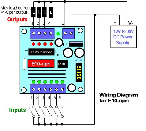
Plc Digital Input And Digital Output Modules Plc Hardware Plc Io Electronics Basics Ladder Logic Plc Programming

Plc With Interposing Relay Plc Programming Relay Power Source

Electromechanical Relay Diagram Electrical Circuit Diagram Electrical Projects Electronics Circuit

Interposing Relay Is The Auxiliary Relay In Plc Which Is Used To Isolate Two Different Syste Programmable Logic Controller Relay Programmable Logic Controllers

Electrical Plc Wiring Diagram On Counters In Ladder Diagrams Ladder Logic Electrical Diagram Ford Courier
Plc Control Panel Wiring Diagram Services Teknoloji

Conveyor Relay Logic Ladder Logic Conveyor Plc Programming

Plc Application For Reduced Voltage Start Motor Control Eep Electrical Circuit Diagram Ladder Logic Basic Electrical Wiring

Learn Cnc Ladder Logic Cnc Controls Learn Plc Programming And Plc Electrical Circuit Diagram Ladder Logic Circuit

Omron Floatless Level Switch 61f G1 Ote Relay Unit Relay The Unit Switch

14 Pin Finder Relay Wiring Diagram For Complete Learning Visit Http Www Electricalonline4u Com 2017 07 14 Pin Relay Base Wiring Diagram H Relay Diagram Pin

Ab Programmable Logic Controller Plc Questions And Answers Suppose We Have An Al Programmable Logic Controller Programmable Logic Controllers Process Control

60 Lovely Allen Bradley Guardmaster Safety Relay Wiring Diagram Safety Switch Relay Electronic Parts

Or Gate Electrical Wiring Diagram Diagram Electrical Diagram

Pin By Clark Roach On Programming Plc Electrical Wiring Colours Ladder Logic Automation Technology

Plc Program For Bottle Filling Ladder Logic Ladder Logic Electrical Circuit Diagram Logic Programming

Awesome Idec Relay Wiring Diagram Power Networking Cables Electrical Panel

Interposing Relay Connection Relay Analog Circuits Digital Circuit

Pin On Electrical Wiring Video Tutorials